Load capacity is not one fixed number. It results from interacting engineering factors: span length, point-load locations, truss size, material grade, load type, support conditions, connection type, and bracing. Ignore one factor, and your setup becomes unsafe. GF-Truss systems document these factors clearly for you.
Key Takeaways
-
Span length is the biggest factor in load capacity. Longer spans reduce the safe load.
-
Material grade and wall thickness affect strength. Higher grades and thicker walls carry more load.
-
Always use load tables and safety factors. Never guess the load capacity.
Structural Factors That Set Load Capacity
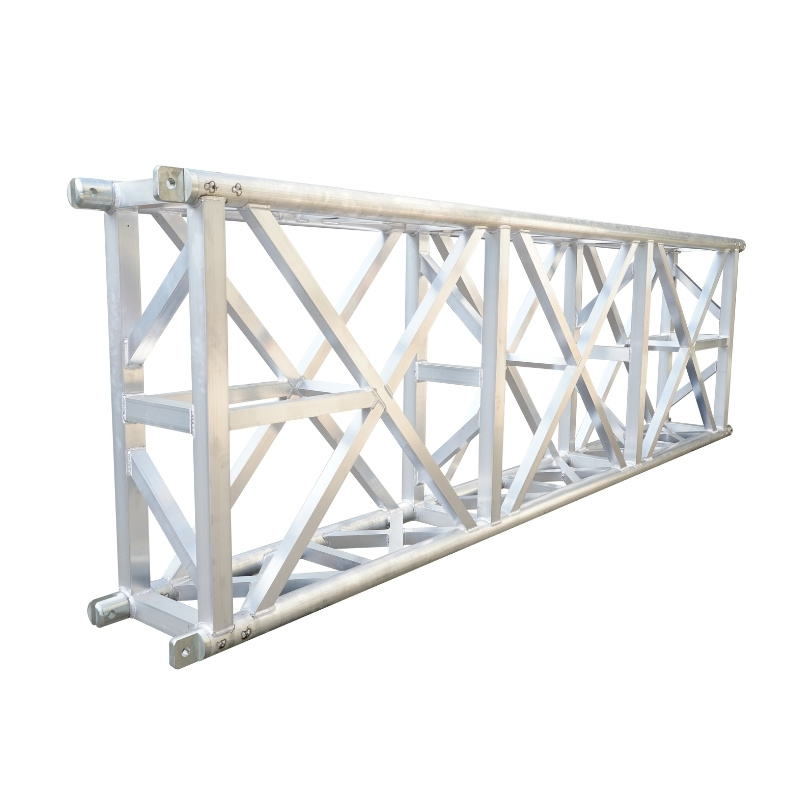
Span, Truss Size, And Material Grade
Span length is the primary selection factor for any aluminum truss system. Maximum load capacity decreases as span length increases. A longer unsupported distance gives the truss more room to bend and deflect under weight. You can see this relationship clearly in a practical example. For example, a truss of a given size supports significantly less load over a longer span.
Material grade also sets the ceiling for performance. Aluminum alloys differ in yield strength, which measures the stress at which the metal permanently deforms. The table below compares two common truss alloys.
|
Alloy |
Yield Strength (Rp0.2) |
|---|---|
|
6061-T6 |
≈ 240 MPa |
|
6082-T6 |
250 – 260 MPa |
A higher yield strength means the truss resists bending under heavier loads. The 6082-T6 alloy reaches a typical yield strength of 260 MPa for extrusion profiles. That extra strength matters when you push spans or loads toward the upper end of a truss series.
Wall thickness works alongside alloy grade. A thicker tube raises the moment of inertia, which is a measure of stiffness. The table below shows how wall thickness changes structural behavior.
|
Wall Thickness Options |
Structural Effect on Load-Bearing Capacity |
|---|---|
|
2 mm |
Baseline moment of inertia; suitable for lower loads and shorter spans |
|
3 mm |
Increased moment of inertia; better for higher loads or longer spans |
|
4 mm |
Highest moment of inertia among the three; critical for high-load or long-span truss series |
The tube acts as a beam. The lowest of bending strength, shear strength, and deflection limit governs the recommended working load. Deflection can control the design even when stress stays acceptable. A span of 2400 mm with an L/240 limit allows only 10 mm of sag. Thicker walls increase stiffness, which raises both bending resistance and deflection resistance.
Load Types, Support, And Connections
You must classify every load that acts on your truss. Dead load is the permanent structure itself — the truss, rigging hardware, and fixed fixtures. Live load is temporary or movable weight, such as performers, lights, or speakers. Environmental loads include wind and snow. Each type affects the total load capacity differently.
Longitudinal chords and cross webs distribute forces through the truss. The chords carry the main bending stress. The webs transfer shear between chords and keep the profile stable. Point-load locations change how those forces travel. A load placed at a node behaves differently from one placed mid-chord. Connection type — bolt, conical, or spigot — also determines how efficiently forces pass between truss sections. Bracing prevents lateral movement and keeps the structure in its designed plane.
GF-Truss engineering documentation gives you verified structural data for every configuration. Always request these documents before you rig.
Using Load Tables To Verify Load Capacity
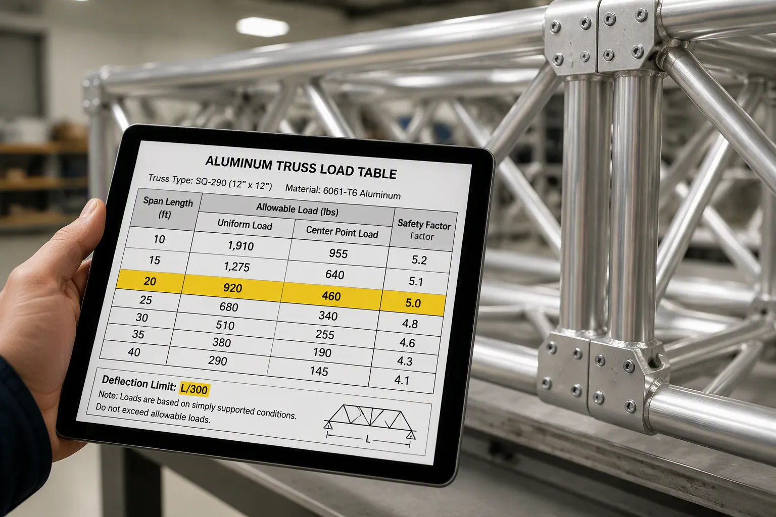
Load tables convert engineering calculations into usable ratings. Manufacturers publish these tables for each truss model and span configuration. You find the allowable load at the intersection of your span length and the truss size.
Reading Load Tables And Safety Factors
Every load table includes a safety factor. This factor separates the ultimate load from the allowable load. You calculate it as the ratio of yield stress to actual stress:
SF = σyield / σactual
A safety factor of at least 1.5 is standard. The table value you read is the safe working load, not the failure point.
Deflection limits also appear in load tables. They control how much the truss can sag under load.
|
Deflection Limit |
Typical Application |
Safety Impact of Exceeding |
|---|---|---|
|
L/240 |
Roof members, industrial buildings |
Ponding water; serviceability issues |
|
L/360 |
Residential and commercial floors |
Bouncy floors, cracked tile |
A limit of L/240 reduces allowable deflection compared to L/180. Many engineers default to L/180 for situations where some visible deflection is acceptable but choose L/240 when greater precision is required.
You must also check the units in the load table. A table listing kg describes mass, not force. Convert mass to force by multiplying by gravitational acceleration. Confusing mass with force is a common source of error in load calculations.
Common Mistakes And Choosing The Right Truss
Rigging errors reduce the load capacity of your assembly. Common mistakes include ignoring span length, mixing connection types, overloading point loads, and skipping documentation. Each mistake shifts forces away from the design assumptions. Excessive deflection makes the system feel unstable long before any actual failure occurs.
Professional documentation must accompany every truss rental. You need manufacturer's load tables, structural reports, and documentation verifying that the published load capacity includes the frequent use factor. Aluminum alloy grade cannot be verified visually. Only a mill certificate traceable to the production batch confirms the material specification.
Choose your truss based on span, load type, and deflection requirement. For high-traffic walkways, select a truss rated at L/300 or stricter. For standard industrial flooring, L/200 may suffice.
Request GF-Truss load tables and professional documentation before you rig. Never guess the load capacity. Always verify with documented engineering data.
Load capacity is a complete system property, not just a truss specification. Your aluminum truss load capacity factors interact. Truss span and load relationships change with truss structural design. You must evaluate span, size, material, load type, support, connections, and bracing together. Request professional documentation and load tables from manufacturers like GF-Truss. Never guess. Always verify.
FAQ
What single factor most reduces an aluminum truss system's load capacity?
Span length drives the biggest reduction. As unsupported distance grows, the truss bends more easily. You must treat truss span and load as one combined value, never separately.
Can two trusses with identical dimensions carry different loads?
Yes. Alloy grade, wall thickness, and connection type all change performance. These aluminum truss load capacity factors work together. A 6082-T6 tube outperforms a 6061-T6 tube of equal size.
Why does deflection matter when stress stays within limits?
Deflection controls the design even when bending stress looks acceptable. A truss can sag visibly before it fails. Good truss structural design keeps sag within limits like L/240 or L/360.